Forum for competition engine enthusiasts. RIP Guy Croft 09/11/2020 - This forum will continue both as a source of information and as a memorial to Guy.
This is my first post so i would like to say hello to all.
i would like to show you Guy my first D.I.Y porting that i started to do to my CVH head and i would like to know your opinions about the work that have been done and if it good ?
Can you advice me how to continue ?
I would like to mention that the first port is not finished yet.
Yes - you are on the right lines there. I actually have a round-port CVH just in to my shop which I shall be starting end of coming week, I will publish the best mods and results in GC V/W if you can be wait...
I have just put the head on test for bare port flow inlet and it's flowing 97 cfm at 10" test depression. My estimate is that with production valve size it may be possible to get it up to, dunno +14% BPF ie: 110cfm. With bigger valves, I don't know - how much flow it wil be possible to achieve to feed a bigger valve (which is after all the arbiter) without breaking through I don't know. Big valves don't make ports flow more, the port is nearly always the controlling regime, put simply, the valve is simply a device for letting it out.
The std port in this case is about 32mm wide by 35mm high, very (very) roughly equivalent to a round port average diameter 33.5mm, so this flow figure ties in roughly (again) with the info on 'how much air will my throttle (etc) flow at: http://guy-croft.com/viewtopic.php?t=679
You can equate the port to a round tube for approximations as to what it will give if ported out. If we go up on port size we're going to see an increase in port flow, though not directly proportional to the ratio of the square of the radii before-after of course.
GC
Attachments
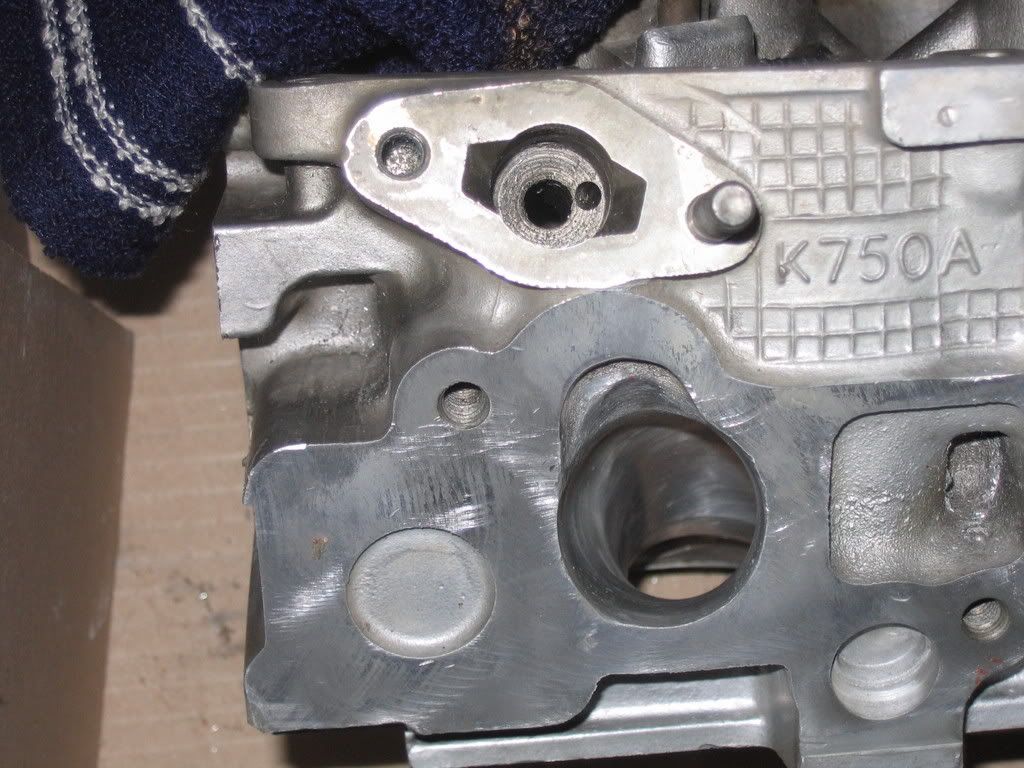
CVH 'round' port head on prelim test to establish flow with no valve, 97cfm at 10" corrected, all said and done quite a lot for a 1600 engine.
CVH BPF as rcd.jpg (114.31 KiB) Viewed 15403 times
Hi everybody, I was browsing the net looking for the info on CVH porting and found your forum. I'm doing my first porting at the moment too.
My head will have bigger valves from burtonpower stainless 43 and 38.75 if remember right... so I'd like to share my work with you.
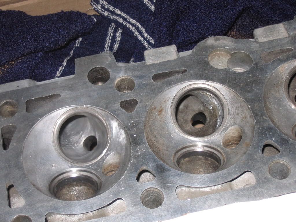
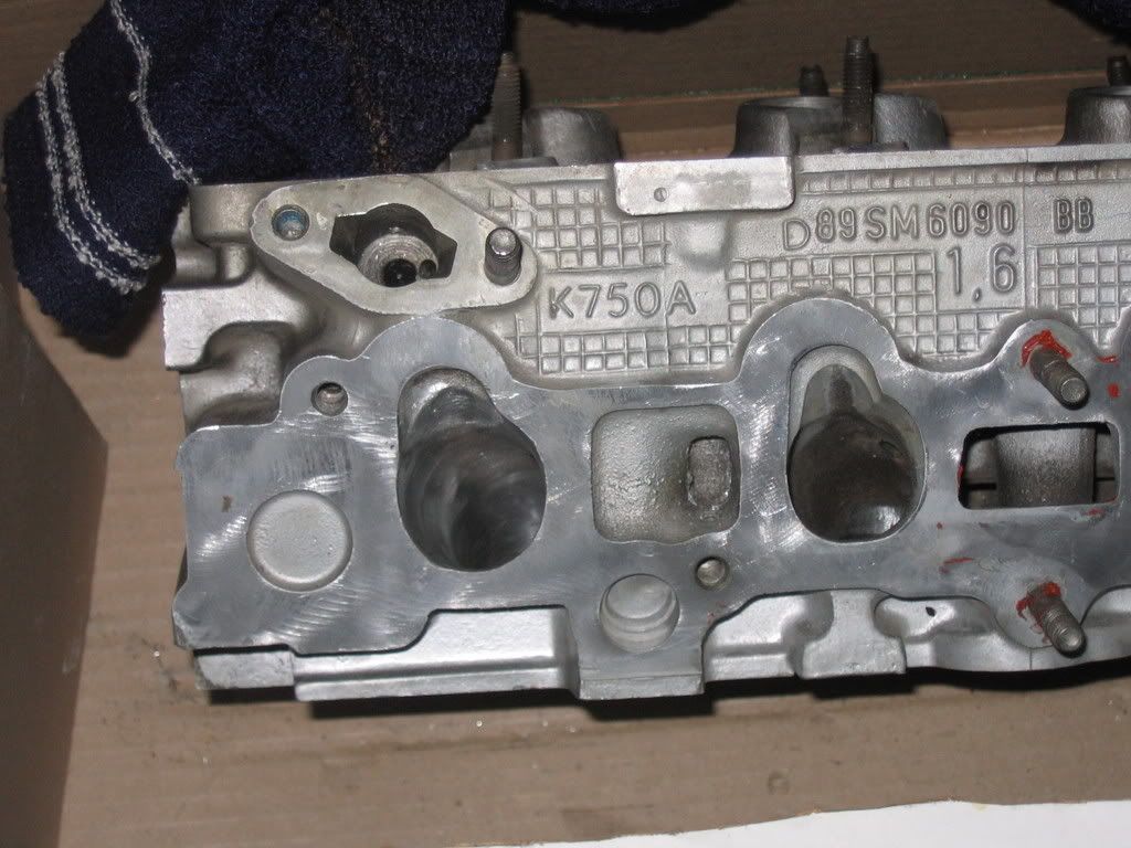
seats where enlarged to match valves and now the porting is taking place.
I'm new to this but I'm trying hard
On the left you see ported port, on the right the port after seat enlargement :)
by the way Guy, penny on the stick type inlet valves should be good on this type of head? as the ones I got from burton are this way :/
P.S. excelent site I keep on reading it for few hours already :)
well done! This site is all about encouraging members to 'have a go' and try out the tuning techniques that I and others write about. It may suprise you to know that some of these important tuning skills are being forgotten - and I don't want that to happen. I know form the letters I get that many people who grew up on 'tuning' as young men in the 70's and 80's are now seniors in the auto industry and I am sure that this is one reason for much more exciting engines! When I did the 'Lotus Lada' - a rather contemporary rally car engine setup on 45 DCOE - I was standing next to a group of senior executives who remarked of the car as it raced round Hethel test track 'why don't our cars sound like that..?' (true)
As for your CVH it's all looking good and I'd be pleased to follow your progress. One important tip I'd like to mention. When you shave the guides, sure it often gives better flow - but it can make it hard to grind or cut a concentric seat. Better to press out the guides before porting and fit aerodynamically better (maybe race material) ones after the porting is done. There will incidentally be a flow loss due to drag frm the rough finish from the rotary burr, small but certainly measurable, finish the ports with 80 grade carburundun paper oiled with WD40 or other light oil. If you cannot get things like ATAbands, you can use a 'split fork' deburrer like this.
GC
Attachments
L-R ATA oval burr, diamond-cut chip breaker, made of tungsten carbide. Garryson fine-pitch alu-cut burr, ATA 'ATAband' - one of the most useful finishing tools ever.
Burrs - porting r.jpg (9.67 KiB) Viewed 15362 times
L-R split fork deburrer - a 12.9 grade M6 capscrew shank slit with hacksaw with 80 or 120 grade tape inserted. ATA 'Polycap' and Atapoint abrasives also good for controlled removal of metal. especially in chambers.
Interesting selection of tools. I would love to find out where to purchase the ATA bands etc.
I buy all my cartridge rolls from the States as they are cheap - but they do have their limits.
Guy Croft wrote:
If you cannot get things like ATAbands, you can use a 'split fork' deburrer like this.
Thanks Guy for the opinion. I will be pleased to share my progress with you.
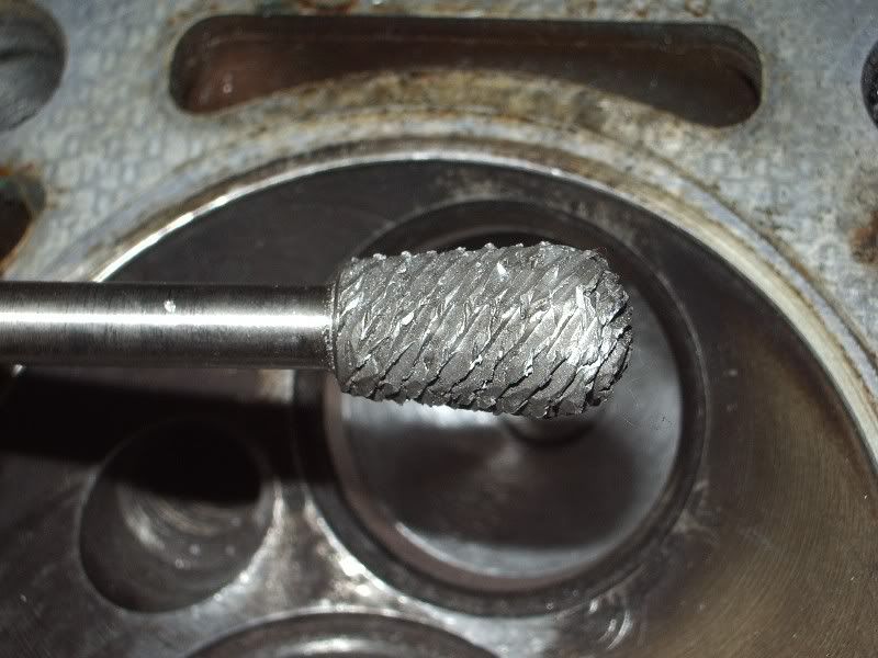
I was thinking about split fork method for the finish, but at the moment I'm using this tool to take the big amounts of alloy
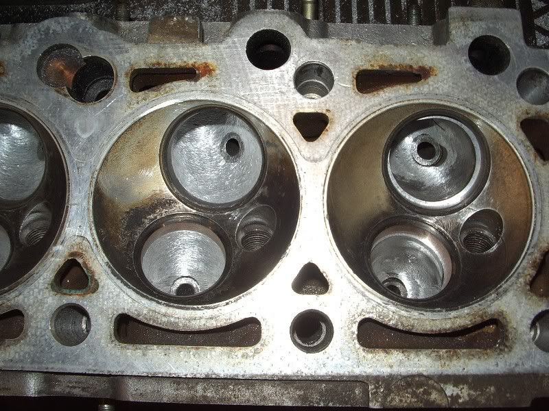
The question would be: Should I polish the exhaust ports to mirror finish? (I know that inlets should be left rough for fuel/air mixture to mix better), but what about exhaust port. I was thinking if I polish them it will prevent carbon building on the port walls. What do you think about that?
I certainly have found a flow benefit from going to 80 grit abrasive finish compared with as-cast, can look a bit untidy especially on 16v ports, I sometimes finish with 120 grit - no gain over 80 grit but because it can look more professional. I oil the abrasive with WD40 or similar and keep the die grinder speed sown otherwise it tends to polish the surface.
I think if you much finer than 120 grit you could lose flow in running conditions, the air boundary layer that exists on stable regions of the port surface may break away and cause turbulence. I don't have the aerodynamic proof of this but I do know some members have done real-time CFD modelling on engine ports and would be interested in their observations regarding the influence of surface finish (or texture as it's more properly called these days under the ISO 9000 eng dwg regime) on boundary layer behaviour.
Understood. I have no problem with the 80 grid texture look :) Will do as you say although I didn't understand what¢ž¢s the purpose of the WD40 here?
P.S. as I look at the job I've done so far I understand that I will not be able to maintain convergence in my ports especially after enlarging the throats to match bigger valves. I there anything I could do about it?
Attachments
slide66_127.jpg (31.79 KiB) Viewed 15512 times
Last edited by Maki on February 19th, 2007, 2:26 pm, edited 1 time in total.
I get all my ATA/Pferd- Procut, Garryson/Morrisflex burrs and accessories from my friend Maurice Bull, MGB supplies, see Links 'engineers' supplies':
ATA do a brilliant little booklet called the 'ATA speed guide and handbook', which shows all their portable grinding tool info, incl bands etc. They are at:
ATA Grinding Processes
Shirland Lane, Sheffield, S9 3FG
Tel: 0114 244 0066
Fax: 0114 244 0099
Garryson make fabulous burrs, the aluminium cut one is especially good, and again, you need to talk to them and get hold of catalogues. This is their website.
That picture of converging/diverging features relates to the port outer region, upstream of the short side radius.
An ideal port would be parallel from port entry right thru to valve throat. That's what downdrafted F1 heads are like.
But on sidedrafted heads with two-valves-per cylinder, especially where the valves are quite large, you often see a divergence from that outer region into the valve throat area. It's obvious that to go from say, a 34mm diameter outer port section to a valve of say, 42mm with 38mm diameter throat, the port will need to expand by 4mm on diameter down there. Although that kind of divergence isn't helpful in developing high flow, you can't generally get rid of it without making the port really huge, which will upset flow velocity and risk breaking into a coolant gallery.
The thing to remember about the valve is that it needs a certain throat diameter to develop good flow, because the loss going thru a single large valve is high. They work well enough, but the bigger the valve the worse the discharge coefficient. Fact is poppet valves are an inefficient way - aerodynamically - of controlling flow, and 4 valve heads work better because two small valves of equivalent throat area will always flow more air than one big one.
Now, having chosen a valve size, one would tend to design the port to flow enough air to feed that valve to the absolute limit, but I have never seen a sidedraft head design where this happens, the ports would have to be enormous. If a designer can achieve the perfomance he needs with a certain port/valve combination - he's happy - even if the flow loss in the port is 20%. To illustrate what I mean. If there was no port outer region, no bend, no divergence, a 38mm valve throat would flow 135 cfm at 10" test depression - a figure no 4 cylinder 8V head has ever got anywhere near here.
The main thing in that region is to develop a short-side radius that really works without setting off turbulence - and to be perfectly honest that is quite impossible to prove-out without a flow bench, and to smooth the region all over.