Fiat Fire inlet manifold revisions and tuning

Road-race engines and ancillaries - general discussion
Lowtechguy
Posts: 43
Joined: January 4th, 2007, 9:38 am
Location: London
Contact:

Fiat Fire inlet manifold revisions and tuning

Post by Lowtechguy »

I have read a few books/articules by David Vizard and of course GC and have had many discussions with various tuners. All this has done is confuse me.

So let me see if I can cover the facts and then get to the questions;
The effects we want to take advantage of are: Pulse charge, ram and scaverging, all these being in tune with induction, inlet, head and exhaust. Change one and knock it all out.

I believe that that longer inlet tracts means the gas speed is increased hence additional torque/lower power curve due to increased airflow at lower revs... But the restriction would be at higher revs as it doesn't flow fast enough.

So....

I have an idea for a modification but am unsure of how to go about it so I wondered if anyone can comment and perhaps get me off the drawing board.

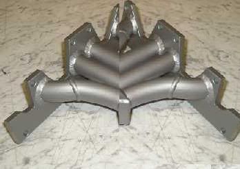
The inspiration was seeing this made by guy croft:

Image

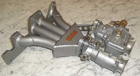
I have always thought of having something like this made (equal length inlet tracts) and I have always thought that the inlet design as standard is compromised and its peak flow would be too high for me to use (12,000rpm or more).

Originally I thought to add a spacer made from the gasket much like what I had done on my 1242 Cinquecento exhaust manifold, this way I can increase the tract of the individiual ports whilst also giving the injectors more room to mix with the air and improve the charge mix without worring about how they are mounted...

The problem with this idea is that I would block the spark plugs after any decent length...

But then the other night I thought about the spacer being tubular like the above picture with the gasket spacer either end of these equal length tubes...

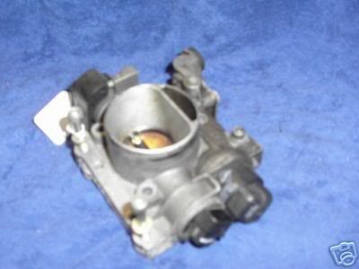
I use a plastic manifold on my car mpi 1.2 8v punto, so cannot port match (there is a cast manifold in the range, however the plastic is a better design to start with plus I have the problems with the ICV, TPS and Map sensor wiring... No thanks) however with the metal spacer I can machine to the right size of the plastic and portmatch the head end etc etc.

I would of course given the nature of the mod want to test it on a flow bench to see if it will work properly (no port being starved) and the mix swirling (or whatever it does, pulsing) as it should but dont know how to start.

What do you think?

Image

This is not showing off my MS paint skills but to get an idea of what I am talking about.

2-4mm gasket sealing face made from gasket as template, 4 tubes of equal length welded and that same gasket sealing face the other side.

Access to sparks no longer an issue and inlet can be increased as much as needed but the injectors staying put in the plastic so they have more chance to mix properly...

I was going to get a first attempt made in the next few weeks but getting it flow tested with a plastic manifold is where I am stuck...

Who would do that, an engineering firm that would make the spacer?

What do you guys think?
Last edited by Lowtechguy on January 11th, 2007, 2:19 pm, edited 1 time in total.
Balidey
Posts: 12
Joined: November 8th, 2006, 1:50 pm
Location: Spalding, Lincs. UK
Contact:

Post by Balidey »

Hello,
I remember you asking the same question over in the Club Cento forum, and for the benefit of the people reading here, the replies were along the lines of...

Too many variables to be able to work out a spacer length straight away. I personally think you would need to make up approximatly a dozen spacers of varying lengths and then try them all back to back to see what results you get.

Another reply stated that just increasing the tract is not necessarily going to give increased gas speed. But I have no experience on this.

My own opinion is that if you are going to the effort of having what is effectivly a new manifold spacer fabricated then you may as well remove the plastic manifold and make a completely new item.

But for the benefit of others, here is a view of what I believe you are trying to make. Very simplified without bolt holes etc.


Image

Regards,
Steve

EDIT: Just to add to this, another comment I have is that you are doubling the number of gasket faces and increasing the number of possible port mismatches. These may not have any affect on the performance of this spacer, but I thought it was worth mentioning.
Lowtechguy
Posts: 43
Joined: January 4th, 2007, 9:38 am
Location: London
Contact:

Post by Lowtechguy »

... this is a small world.

Yes I remember the replies, I was more interested to see what people here would say on the subject as I think they may of made something along these lines whereas I don't think anyone on clubcento would have.

Making a new manifold from scratch would be very nice indeed but the development would be way behond my means.

The idea of using the exisiting manifold was more to do with being able to port match something and also to increase tract lengths.

There have been a number of articules on induction length in the states ( http://autospeed.drive.com.au/cms/A_107749/article.html ) and a company I use often swears by this also.

The idea was not to re-invent the wheel more to make it abit slicker. I know this won't do the world but if it brings the power band down lower alone then its worth it.

I think the test version will be made of variable lengths to test in one day, establish the length and go from there, what I was hoping to gain from this post was to gain advice on how best to start. I know a book can be written on port shape but a few tips on how to start would of been cool.

Thanks for the picture though bailey, I cannot draw well..
Balidey
Posts: 12
Joined: November 8th, 2006, 1:50 pm
Location: Spalding, Lincs. UK
Contact:

Post by Balidey »

I have just had a quick scan of that article and the increase in length is BEFORE the throttle, not after as your spacer would suggest is what you are trying to achieve.

My suggestion as to why this works (and please note I currently have very limited knowledge on engine tuning, it is just my common sense) is that after the air filter the air must be very turbulent and therefore slow. If a filter is close to a throttle then the air may be slower than if the filter is moved away from the throttle and has settled to a more linear flow by the time it reaches the throttle. This seems to be proved in that article.
Lowtechguy
Posts: 43
Joined: January 4th, 2007, 9:38 am
Location: London
Contact:

Post by Lowtechguy »

Hello again,

The link was just an example, inlet length counts from the port to the air opening as a whole.

But I am not refering to induction as I have this sorted, it was just a cheeky way to lower the power band and increase torque hopefully by giving a longer (and striaght) run to the port as well as mixing of charge pre combustion chamber
benlilly
Posts: 52
Joined: July 21st, 2006, 10:47 am
Location: Stroud, Gloucestershire
Contact:

Post by benlilly »

Hi Guys,

I'm also looking at inlet manifolds at the moment and, in a few weeks, should have a new custom manifold for my car.

It is going to be made by a company called Bogg Bros. The are based in N. Yorkshire. I'm sure they could make the spacer you are looking for.
http://www.boggbros.co.uk

This was all started from some flow measurements made by Guy on the OE manifold. The problems related to the entry direction where the manifold met the ports.
http://guy-croft.com/viewtopic.php?t=229

In the article posted it's interesting that they found such big improvements altering the length after the throttle plate. Presumeably there was some sort of chamber on the engine side of the throttle and I would have expected this to damp the pipe resonances that would increase cylinder filling and in turn, power.
Guy Croft
Site Admin
Posts: 5039
Joined: June 18th, 2006, 9:31 am
Location: Bedford, UK
Contact:

Post by Guy Croft »

For the engine getting this new manifold - please cite the full engine spec so I can understand better what you're doing.

Especially I need to know the cam type & timing, fuel system and exhaust header setup. Try to be detailed but concise.

GC
Lowtechguy
Posts: 43
Joined: January 4th, 2007, 9:38 am
Location: London
Contact:

Post by Lowtechguy »

I am sorry if I come across vague, I'm not in the trade so may not express myself as well as I would like.

I suppose I should start from the begining to be clearer.

Last year my spec was:

Fiat fire engine 1.2 8v 60bhp.
Punto 75 camshaft
Ported and flowed head
Induction kit with 100mm BMC twin cone filter approx 1 meter long
Raised compression approx half a point to 10-1 (standard 9.6-1)
3 Angle Valve Cut
Standard throttlebody 32mm
NGK 7 Heat range (Wrongly adviced by a mechanic to go colder)
Supersprint exhaust manifold
Sports cat 200cell
Supersprint centre section box
Supersprint Backbox Twin exit

I had it rolling roaded and got 74bhp without mapping.

After the remap I had 94bhp @ 6528rpm and 87ftlb @ 6124rpm of torque.

With the car running lean I had no problems with the 7 range plug but when the fueling was increased the engine started to coke and I was getting misfires at 5,000rpm approx on load. this increased throughout the rev range until it had problems starting - I thought the problem was with the mapping but it was the plugs.

I changed to the stock plugs (5 range), many gas treatments later the engine is happy again.
Since then I have wanted to get over the 100bhp mark and aim for the 120bhp mark as I believe this is possible if the hardware is right this time before mapping.

I had the cam re-profiled, the figures have not been told to me apart from its a fast road cam not a peak power cam but it has 290degree inlet and exhaust, so far there has been an increase in lower down power than before.

I am getting a throttlebody machined to enlarge it to 40mm (it is possible to go 43mm but I was told this is too much).

I was disapointed with the power being so high and I am not the sort of person that can justify mapping sessions to just get it done again a few weeks later so I was hoping to lengthen the inlet tract in order to bring the whole power curve to the left (as you look at the rolling road graph).

I don't want to re-invent the manifold just improve on it, I cannot port match as it is plastic.

Does that make any more sence?
Guy Croft
Site Admin
Posts: 5039
Joined: June 18th, 2006, 9:31 am
Location: Bedford, UK
Contact:

Post by Guy Croft »

As a rule of thumb mostly you'll get more bottom-end and mid range torque at the expense of peak power by lengthening the inlet tract.

I cannot say what effect enlarging the throttle body will have really but I suspect none at all, a 32mm throttle body will flow 96cfm which is no impediment to power on a 1.2 liter engine, a 2 liter 131 head flows that out-of-the-box!

Your torque is very good, you'll spend a lot to get much closer to the peak for that 1.2L 8V motor, around 94lbf ft, but the bhp might be something you can improve. It's developing peak poewr a bit low really, losing torque at the top end. That could well be a breathing problem and I doubt that you'll get any significant increase from anything consisting of a 4-1 inlet manifold or one with inlet tracts linked into a common plenum. The inlet pressure waves get all mixed up, go throttle 40mm bodies etc Jenvey Omex if you want it to fly.

If you don't want to go to that expense there are other regions where gains might be had, but the inlet manifold could well hold you back, and as I say lengthening it will rob bhp not the other way round. I'm talking about things like superior camshaft, checking out the head work etc.

I do feel bound to remark that the output is HIGH for a production bottome end if that is what it is, borderline not very safe actually - and you really should put your money into race rods and pistons before doing any more power mods. Only my advice...
Lowtechguy
Posts: 43
Joined: January 4th, 2007, 9:38 am
Location: London
Contact:

Post by Lowtechguy »

Guy Croft wrote:As a rule of thumb mostly you'll get more bottom-end and mid range torque at the expense of peak power by lengthening the inlet tract.
This is mainly a road car so that sounds up my street (I would prefer torque over big BHP in a rev range I wouldnt use).
Guy Croft wrote:I cannot say what effect enlarging the throttle body will have really but I suspect none at all, a 32mm throttle body will flow 96cfm which is no impediment to power on a 1.2 liter engine, a 2 liter 131 head flows that out-of-the-box!
On a stock engine the increase was rolling roaded at 7bhp and 10nm (sorry I dont know what that is is Ftlb), how this effects my car I don't know but it did just seem the logicial next step of "what you can't get in..."
Guy Croft wrote: Your torque is very good, you'll spend a lot to get much closer to the peak for that 1.2L 8V motor, around 94lbf ft, but the bhp might be something you can improve. It's developing peak poewr a bit low really, losing torque at the top end. That could well be a breathing problem and I doubt that you'll get any significant increase from anything consisting of a 4-1 inlet manifold or one with inlet tracts linked into a common plenum. The inlet pressure waves get all mixed up, go throttle 40mm bodies etc Jenvey Omex if you want it to fly.


My car has a can bus system to regulate the electronic steering to name 1, so aftermarket systems have always been a no no. Some Jenvey throttles do sound very tempting but after what I have seen of a certain hyabusa conversion I wasn't impressed with the torque output or delivery with t/b's of that size on this sort of engine.

Guy Croft wrote: If you don't want to go to that expense there are other regions where gains might be had, but the inlet manifold could well hold you back, and as I say lengthening it will rob bhp not the other way round. I'm talking about things like superior camshaft, checking out the head work etc.
So in principle you think I should leave the inlet alone? As previously said I much prefer torque and its smooth delivery against peak power as just raising the revs will get the boasting rights on paper, I am after real world acceleration.

The manifold I know is a tricky one to answer, its one thing to drive a car another to explain how and like yourself you'dneed to know what you're doing (which I don't) so I do understand your position.

However I really thought it would have opposing reations to which a compromise could be established, i.e;
- the fuel mix/charge would have longer to develop/mix (direct port injection being on the road car but f1 cars have it a few mm above the throttlebody, however the extreme with that is idling at 4,000rpm as it is in perfect position for the high revs the engine does).
- with the striaght run just before the gas speed would increase, however as you say the longer the route the more turbulance created and longer reation time from opening to valve. So I figured that with various testing I would be able to find some compromise between the two opposing factors.

I was only thinking 50-80mm extension?
Guy Croft wrote: I do feel bound to remark that the output is HIGH for a production bottome end if that is what it is, borderline not very safe actually - and you really should put your money into race rods and pistons before doing any more power mods. Only my advice...
I was always under the assumption that the largest stress on the engine was the connecting rods and the biggest stress on them is the exhaust stroke, I know of several 1.2 turbo engines with standard blocks bar the decompression plate (if that counts) with as much as 130ftlb, something I doubt I would ever reach, however you are right, it is something that will get attention but only when I can get my hands on the 1368cc fire unit and swap over when the work is finished.
sumplug
Posts: 234
Joined: June 25th, 2006, 10:25 am
Location: Banned 4th Oct 07 by GC
Contact:

Post by sumplug »

Just a thought, the twin exit exhaust will be robbing you of power/torque. It will cause a bottleneck problem along the length of the system. A single exit of around 2 inches will be all that is needed, If it's looks you want, keep the twin setup.
The car on Hyabusa's, Not coloured purple or silver?
Ive seen some tuned Fire engines, and yours is making well above average, average being 78bhp-85bhp. Your head must be flowing very well.
What fuel pressure are you using? Standard? Ive heard of 36mm and 38mm T/B's used on these engines. Plastic manifold is useless and needs ditching.

Andy.
Lowtechguy
Posts: 43
Joined: January 4th, 2007, 9:38 am
Location: London
Contact:

Post by Lowtechguy »

sumplug wrote:Just a thought, the twin exit exhaust will be robbing you of power/torque. It will cause a bottleneck problem along the length of the system. A single exit of around 2 inches will be all that is needed, If it's looks you want, keep the twin setup.
The car on Hyabusa's, Not coloured purple or silver?
Ive seen some tuned Fire engines, and yours is making well above average, average being 78bhp-85bhp. Your head must be flowing very well.
What fuel pressure are you using? Standard? Ive heard of 36mm and 38mm T/B's used on these engines. Plastic manifold is useless and needs ditching.

Andy.
Thank you.

The plastic manifold is nice and smooth being a dry manifold afterall, however the cast from the earlier mpi model (punto 75) requires some sensors to be messed with and tbh I can see that go wrong very quickly.

The fuel pressure is standard at 3.5bar.

Thats a good point about the exhaust, it is a supersprint also but it was all that the uk distrubtor had in stock... (I wanted the single oval really)...

There is a 32mm one as standard on this engine MAGNETTI MARELLI type.
Image

The rolling road graph I have seen was of the silver (andrews) one and we compaired this graph against a stock engine with supersprint and proper induction revision and our engine had more torque throughout and more horsepower until 6,000rpm or so. I know he has had further mapping and possibly other modifications since but at the time against the comparision it didnt look good.
Guy Croft
Site Admin
Posts: 5039
Joined: June 18th, 2006, 9:31 am
Location: Bedford, UK
Contact:

Post by Guy Croft »

Well you're right about the highest inertia but that's not the whole story and in my exp unless the rods or bolts are ancient or cracked it's more usually the cast piston that lets go first. Often misdiagnosed as rod/bolt failure. The stress thing is a bit off topic, so I was just hinting there. It would truly be better in a new thread but I'd definitely need a piston and con rod to evaluate the limits. In the meantime have a read of:
http://guy-croft.com/viewtopic.php?t=200

An interesting thread and I'll get back to you on it later. The odd decent detailed photo would add a bit more interest - please!

GC
sumplug
Posts: 234
Joined: June 25th, 2006, 10:25 am
Location: Banned 4th Oct 07 by GC
Contact:

Post by sumplug »

Also on the Fiat 'Fire' engine, crankcase mods to alleviate aerating of the oil are highly recommended. Can add a few HP to the engine. I know other tuners knife-edge the crank. There are some who like it, and some who discard it as a waste of money!!
Regarding Andrew's car, wasn't it a 16v engine?

Andy.
Lowtechguy
Posts: 43
Joined: January 4th, 2007, 9:38 am
Location: London
Contact:

Post by Lowtechguy »

sumplug wrote:Also on the Fiat 'Fire' engine, crankcase mods to alleviate aerating of the oil are highly recommended. Can add a few HP to the engine. I know other tuners knife-edge the crank. There are some who like it, and some who discard it as a waste of money!!
Regarding Andrew's car, wasn't it a 16v engine?

Andy.
Which do you suggest, dry/baffled sump or knife-edging or both?

It was a Fiat Punto mk2 16v
Post Reply

Who is online

Users browsing this forum: No registered users and 80 guests