16v integrale - Custom Inlet manifold project (lots of pics)

Competition engines and ancillaries - general discussion
tricky
Posts: 101
Joined: July 6th, 2010, 5:41 pm

16v integrale - Custom Inlet manifold project (lots of pics)

Post by tricky »

Hello Guy and forum members,

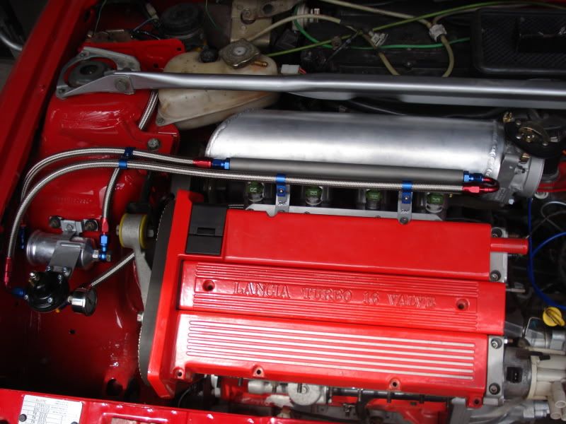
I was in two minds if this would be better suited to the 'road' discussion area as the car is primarilly a road car but since we're talking about the engine and it's a fairly ambisious one I decided to post in this area.

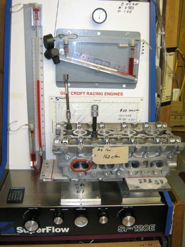
There has been lots of talk on this forum and other well known Fiat / Lancia ones over the years about inlet manifolds on the 16v turbo variants. What we do know is that generally speaking the OE manifolds in the form of Coupe, integrale and kappa all suit the untouched heads in CFM flow and tuning terms. So as we modify our cylinder head's inlet ports the OE manifolds just get steadily worse (effecitvly going backwards). For example the 16v head BPF (Bare port flow) is 133 CFM @ 10" and the Integrale manifold 125 CFM, which is barley enough to keep up with the 'as cast' head. After porting the head can reach 165 CFM in the highest state of tune, therefore bolting on an inlet manifold with 125 CFM is'nt going to give you the most from what the cylinder head ports are (very) capable of.

GC rule, " The manifold must match or outflow the head"

The options are quite plain, 1> Use another version of an OE manifold and modify, or
2> Build one from scratch.

I went for no. 2 and here is why,

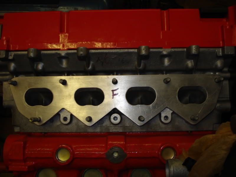
Lets look at the OE options first, the integrale manifold is a bit of a lost cause because it would need to be extensively cut into bits to allow porting and then welded back together agian, even then the plenum is too small for high output engines and the runner length is tuned to work at low to mid rpm. The coupe / tipo unit is more promising due to the fact that the runners can be seperated from the main plenum, this alows for some nice porting to be done internally of which I know Guy has tested this method and achevied just a few CFM loss when bolted to a modifyed head on the flow bench. Unfortunatly the same problems arise with the inadequete plenum volume and fixed runner. One other feture of the coupe manifold is that it curves up to the head which works, but we have a downdraughted head and a matching downdraghted manifold would be preferable. This brings me to the Kappa, this has nice down draught angle and a slightly larger cross section in the runners yielding better overall flow over the others, problem with the kappa unit is fitting it in the integrale engine bay as it's quite tall and again same fixed dimentions like the others. The kappa can be ported from the entrance and back slightly to flow (correct me Guy if 'm wrong) 148 CFM @ 10 ". Not bad, but not quite enough for our 160 CFM head, so using any of the above, while good in some areas were allways going to be a copromise.

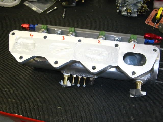
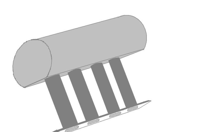
Here's what I did and how I did it, this is the basic design drawings I made before hand - with a bit of help from the workshop manual :-)

Image

Image


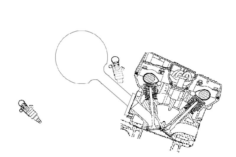
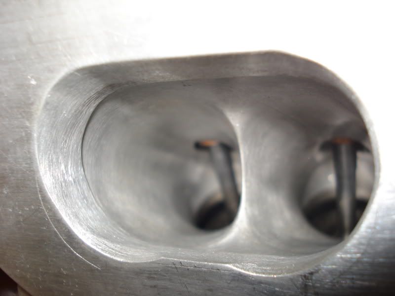
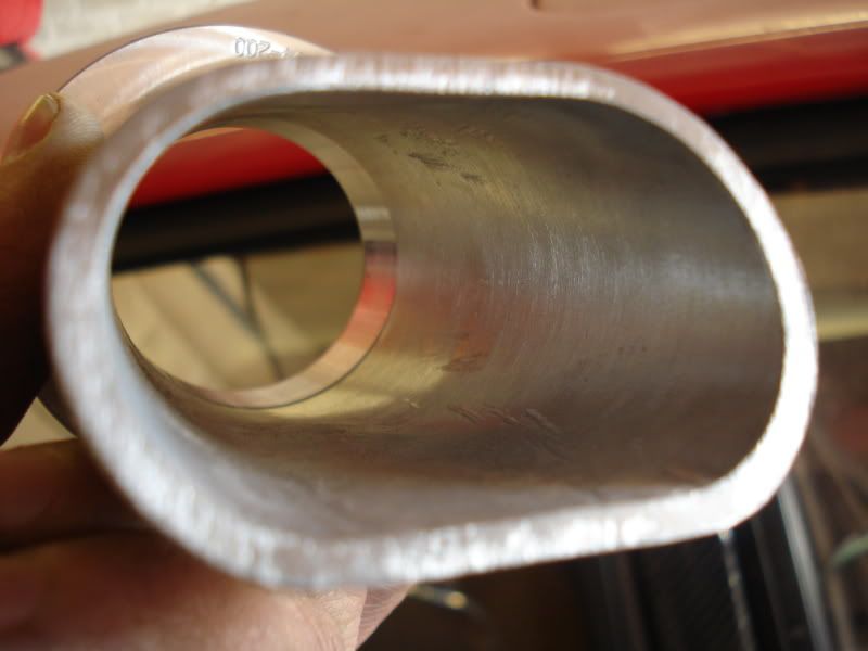
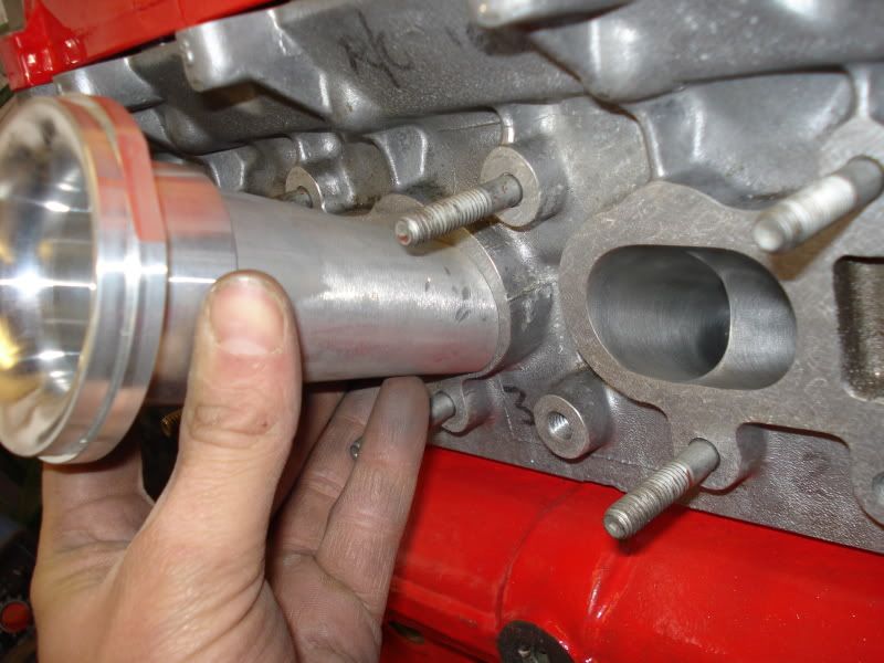
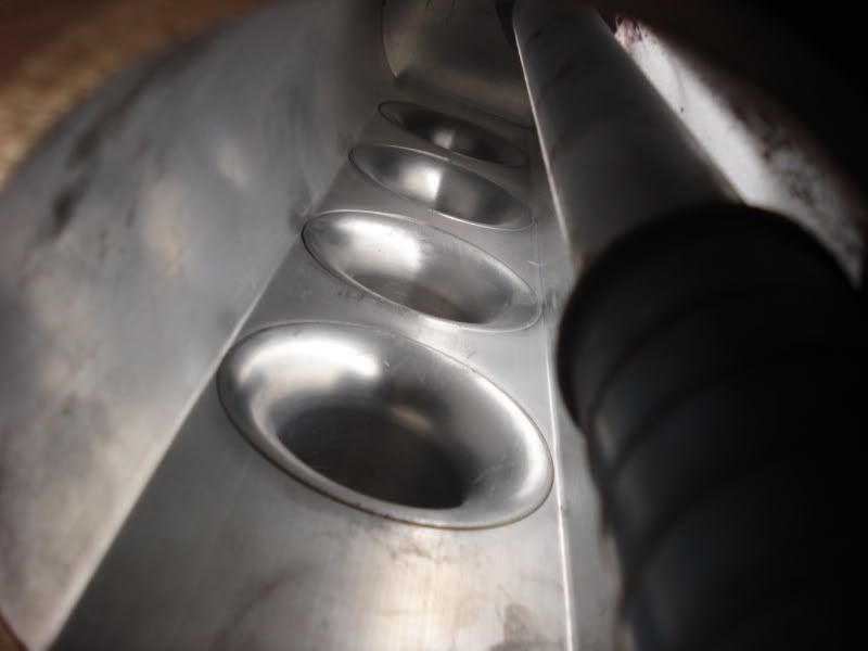
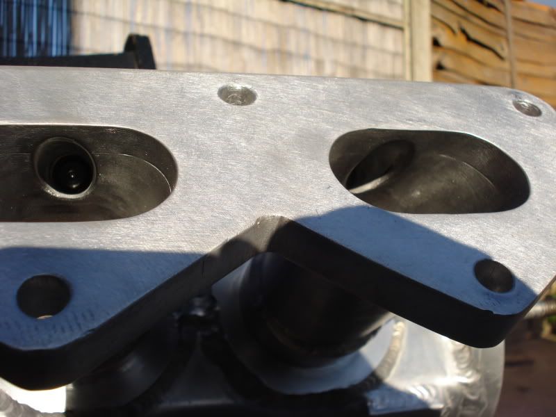
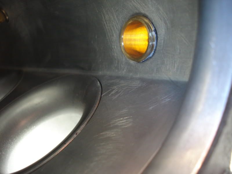
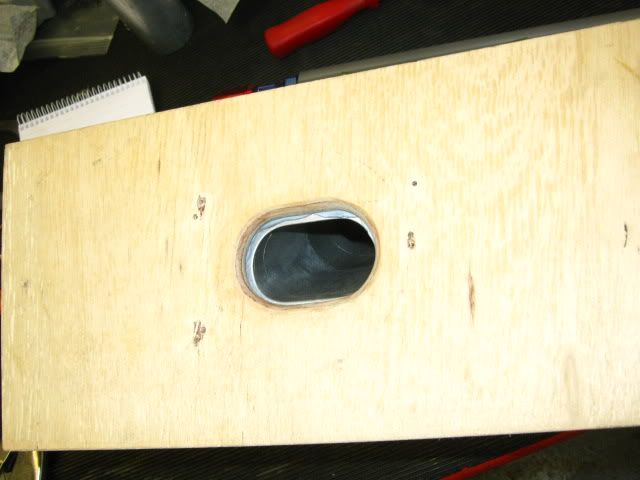
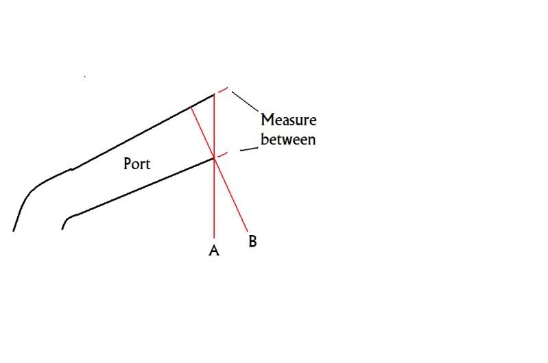
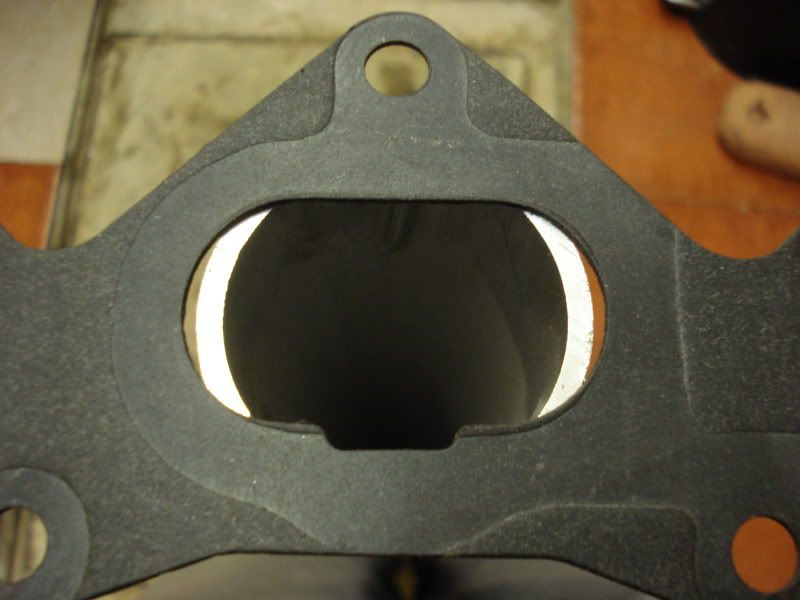
First job is to work out the cross sectional area of one inlet port, this sounds straight forward enough but the area is deceptively large. To get the true size you need to measure across the port perpendicular at 90 deg and not across the gasket face which is quite a bit larger due to it's diagonal plane. See picture below, measure line 'B'.

Image

To find the area we also need the distance accross or the horizontal plane, then break it up into sections with a diagram (see below). So what we effectivly have is a rectangle and two semi circles which is easy to find the area from here. To find the middle dimentions simply subtract the height (diameter of circle part) from the width giving us the 24mm.

Image

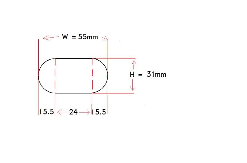
Area of inlet port = area of rectangle + area of circle (2 x semi's)

Area of rectangle = 31 x 24
= 744 sq mm

Area of circle = radius squared x 3.142
= 15.5 x 15.5 x 3.142
= 754.8

Add the two areas - 744 + 754.8 = 1498 Sq mm, which translates to a round pipe with an ID of 43.5mm

Materials list so far-

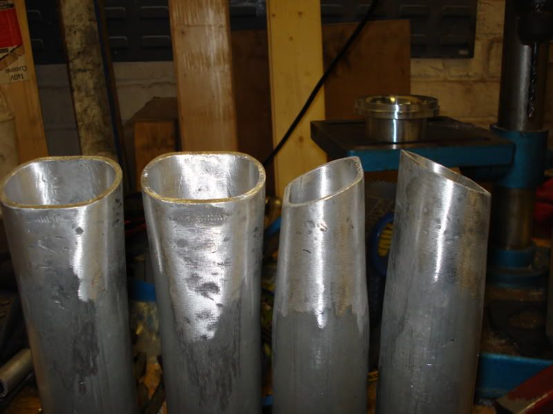
Alluminium tube 2" od x 10 SWG 1 meter off (runners) around 44mm ID
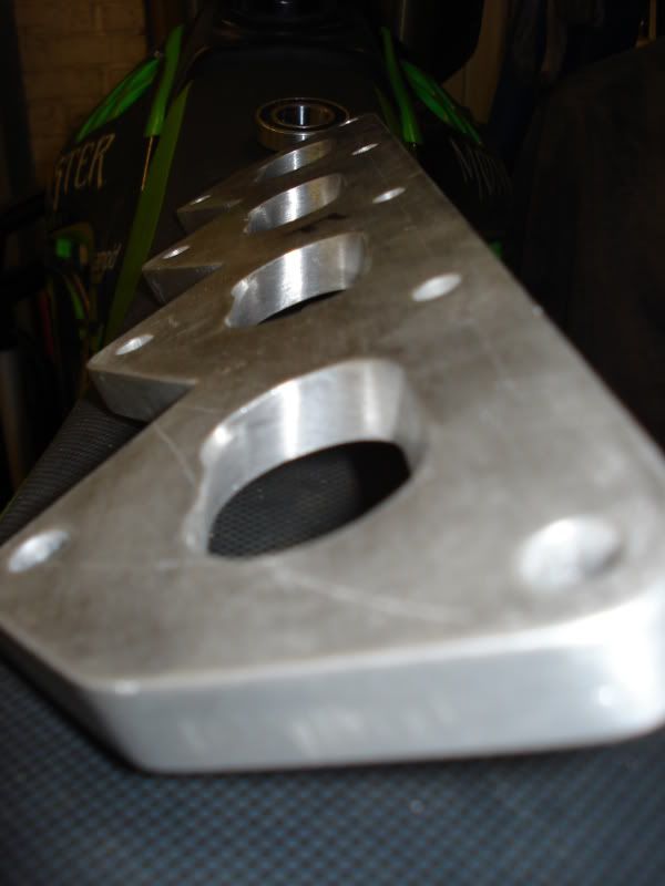
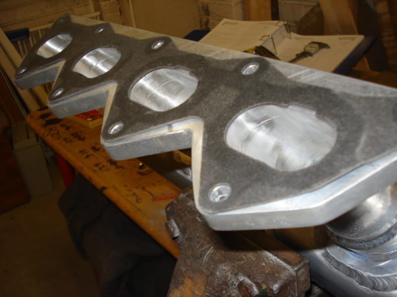
" Flat bar 4" x 1/2' (flange)
" Flat bar 6" x 1/4' (plenum end cap)
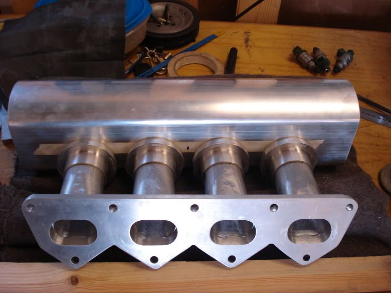
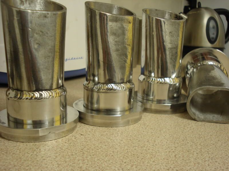
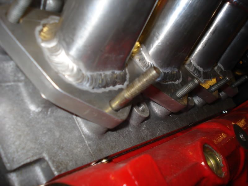
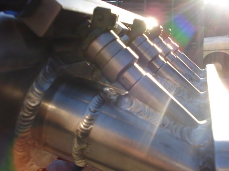
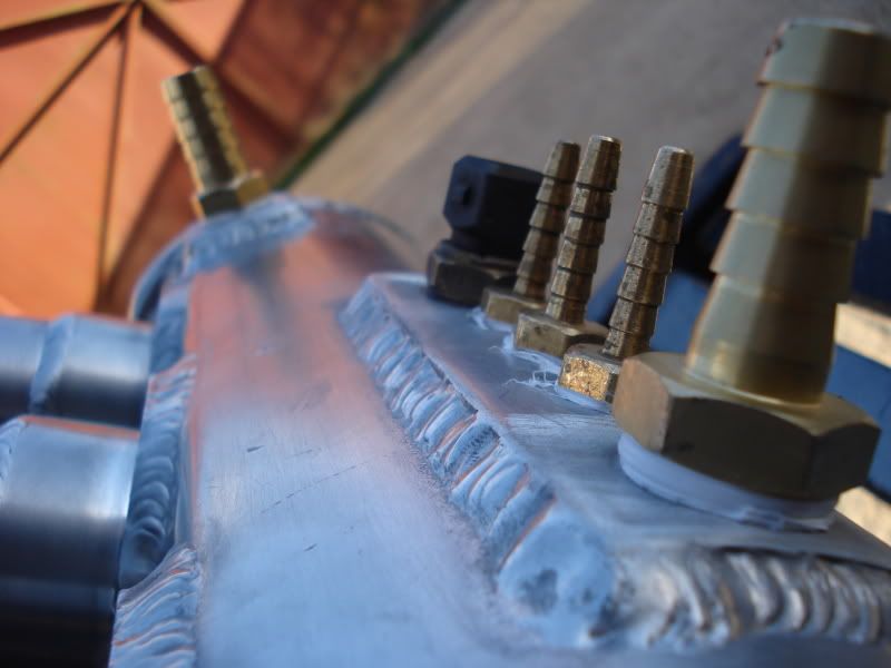
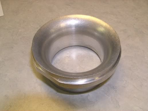
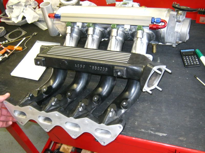
I sourced the plenum extrusion, some 2" weld on ram pipes and a blank fuel rail from a firm in the states who specialize in inlet manifold parts, send me an email for more information. The plenum is a solid one piece 1/4" thick extrusion and the ram pipes are made with a lip which fits 2" tube perfectly.

Image

Image

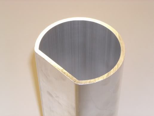
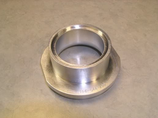
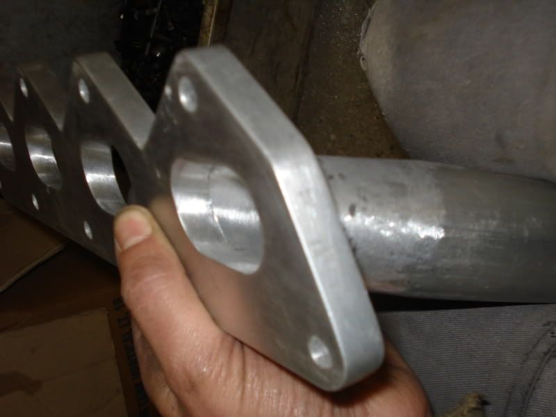
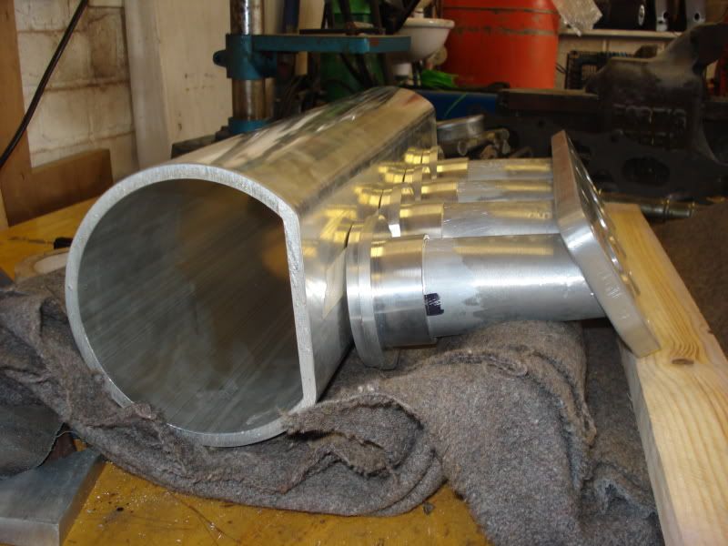
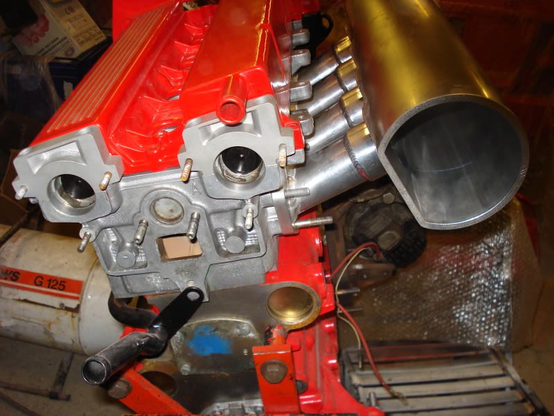
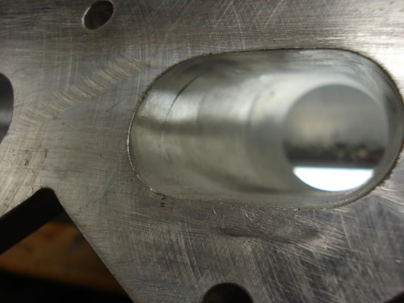
And here is the round ally tube and what will be the flange.

Image

Image

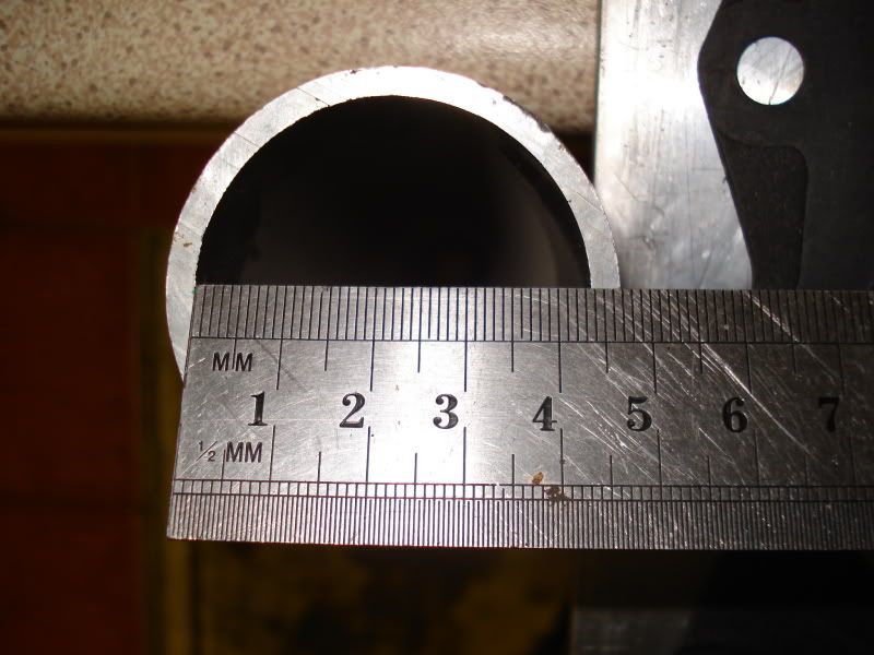
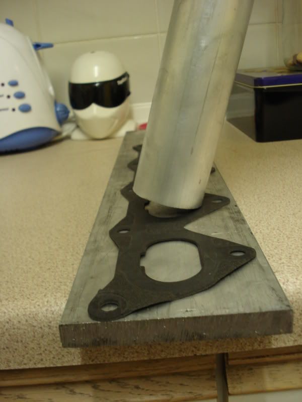
Does'nt quite fit the area yet !

Image


Thats it for part 1, I will cover the actuall building technique next time.

Richard
Twice as many valves
Guy Croft
Site Admin
Posts: 5039
Joined: June 18th, 2006, 9:31 am
Location: Bedford, UK
Contact:

Re: 16v integrale - Custom Inlet manifold project (lots of p

Post by Guy Croft »

MODEL POST!

GC
tricky
Posts: 101
Joined: July 6th, 2010, 5:41 pm

Re: 16v integrale - Custom Inlet manifold project (lots of p

Post by tricky »

So part 2 . . . Building it.

The flange is easy enough to cut to shape by laying the gasket out onto the flat bar and scribeing round it, adding some extra meat in some areas to allow for the thickness of the tubes and the welding. A pillar drill comes in handy for making the holes for the manifold studs to pass through and if you take your time to drill the centres acuratly, just a little bit of filing is needed with the round file to releive them. Once you have the shape of the blank flange and can fit it to the head snugly, offer the gasket up and mark the port's entry shape onto the blank. Because this is to be a downdraughted manifold the angle of the port needs to carry through the flange as well, so mark this out carfully if doing it from the 'back' side of the new flange. Then using a smaller than nesacery hole saw continue to cut out the 8 holes.

If you follow what I mean you should have something that looks like this. . .(F means - don't put it on the wrong way round)

Image


The newly made four oval holes need to be ported out to match the shape of the inlet ports, I achevied this first off with a burr one port at a time with the flange in a vice, keep removing metal bit at a time then offering it back to the head to check. Pay carefull attention to the angle by keeping the die grinder in the same position, I found it helps to get a bit of steel welding 'filler' rod, grind a sharp point on one end and bend it back on it's self then you can scribe the exact shape onto the flange from the port side with the flange bolted upto the head. Finnish off with 30mm flap wheel to get the corners nice.


This picture shows the flange porting - nearly completed.

Image

Image


One major difficulty here is symetry, especially when it comes to the runner shape. Use a combination of a steel rule and a vernier locked at the dimention you need, to copy over to the next one. In order to shape the end of the runner into an oval, I had all sorts of ideas about this but the easyist way is to cut the alluminium tube up into four sections, heat one end up evenly to make it plyable and literaly beat it into shape with a hammer. I found the perfect tool for this in the form of a solid iron bar 30mm in diameter and clamped in the vise to make a nice anvil to form the corner shape into the tubes. I used a typical plumbers gas torch.

Here they all are, I roughly cut the needed angle onto the ends before finishing and matching the shapes perfectly can you see the hammer marks ?

Image


This is the finnished shape of one, and offering them up to double check size and shape agianst the new flange.

Image

Image


The tubes all need to be cut on thier ends to find the best angle to follow into the port, here I used several straight edges placed along the port floor and roof to determine the best line of sight to the back of the valves. Getting them all the same is easy, a draper mitre saw (meant for wood) I found cuts ally like a piece of cake and staright and repeatable. On the second photo you can see the wide entry radius and hopefully you have a fairly good runner to port match by now, which can be corrected a litte later if needs be.

Image

Image


The length of the runners is determined from a calculation of - valve event timing, inlet air temprature, engine speed and runner diameter. The basis of which is to trap a 'harmonic reflection' to work for us at a certain engine rpm. There are many calculators plastered on the internet to work this out for you, each of them give a different answer. Without going into a whole other subject too deeply, all I will say is that the most trusted way I found to estimate the effects is by longhand calculation. These are cut to length and 'tuned' to 7000 rpm.


After transfering the spacing to the plenum in a mock up, it all starts to come together nicely. The 4 times 2" holes were cut into the floor of the main chamber for the ram pipe sections, they are designed to finnish flush on the inside of the plenum. I have two different welders, but neither of them capable to weld aluminium and not having had the experience so I made the choice to get someone to do it for me in three stages. Firstly the individual runners onto the ram pipe's, this gave me the opportunity to smooth the inside all the way through with a large flap wheel. Then with the help of a jig made to clamp the whole lot together using two lengths of timber and various straps for second welding, pictures tell the whole story, notice Guy's porting is nicer than mine ;-)

Image

Image

Image

Image


After the second stage of welding is done a skim to the flange is needed and a little corrective porting between runner and flange, it looks like this . . .


Image

Image

Image

Image

Image


For final welding another jig had to be made consisting of a flat steel bar with four (injector) sized pins attached, placed at bore spacing along it's length. The injector bosses themselfs were sourced from the same company who supplied the ram pipes and plenum, these had to be cut at the narrowest angle posible, and placed as close to the back of the flange as posisble to ensure the injector fires to the back of the valve. I pilot drilled the holes first and after welding ported the injectors into the runner with an outward flare, again symetry is important. The plenum was cut at an angle and an end plate rolled to shape and some blocks welded to support the fuel rail along with some reinforcing for the hose take-offs on the underside. In the last photo here you might just make out, the throttle body plate has a radius on the back done suprisingly well with a wood router !

Image

Image

Image

Image

Image


Thats all for now, next time I'll show you the finnished manifold and some flow testing .


Thank you for reading, Richard
Twice as many valves
TR-Spider
Posts: 132
Joined: June 23rd, 2006, 8:37 am
Location: Rekingen / Switzerland
Contact:

Re: 16v integrale - Custom Inlet manifold project (lots of p

Post by TR-Spider »

Congratulations, that is a stunning job!

Thomas
GC_23
Simon
Posts: 145
Joined: August 1st, 2009, 6:55 pm
Location: Leicester
Contact:

Re: 16v integrale - Custom Inlet manifold project (lots of p

Post by Simon »

Some superb engineering there Richard!
GC_15
TomLouwrier
Posts: 333
Joined: July 28th, 2010, 3:09 pm
Location: Leiden, The Netherlands
Contact:

Re: 16v integrale - Custom Inlet manifold project (lots of p

Post by TomLouwrier »

Really good to read stuff like this. And hats off for your fabricating!

regards
Tom
GC_29
tricky
Posts: 101
Joined: July 6th, 2010, 5:41 pm

Re: 16v integrale - Custom Inlet manifold project (lots of p

Post by tricky »

Thank's fellas, that means a lot to me.
Twice as many valves
WhizzMan
Posts: 459
Joined: August 13th, 2010, 8:05 pm
Location: Amsterdam, the Netherlands

Re: 16v integrale - Custom Inlet manifold project (lots of p

Post by WhizzMan »

Very nice engineering and great to share the how to with us. Did you keep the trumpets level with the "bottom" of the plenum on purpose?
Book #348
tricky
Posts: 101
Joined: July 6th, 2010, 5:41 pm

Re: 16v integrale - Custom Inlet manifold project (lots of p

Post by tricky »

Yes, the plemun walls make a nice feed into the trumpets or ram pipes which keeps the interior smooth and turbulance down. Some people build the trumpets up high into the middle of the plenum with a big roll back radius on them to help draw air in from behind the ram pipe, but since were talking about a sealed chamber thats not open to atmosphere like say a carburetor inlet horn, I don't see the benifet.

The inlet radius has a 1/4" deep step built in around the edge so it fits square into the main floor.

Image
Twice as many valves
Guy Croft
Site Admin
Posts: 5039
Joined: June 18th, 2006, 9:31 am
Location: Bedford, UK
Contact:

Re: 16v integrale - Custom Inlet manifold project (lots of p

Post by Guy Croft »

the capture from a rampipe is only from the front anyway and mostly concentrated at the centreline - unless you starve it by placing an object like a plenum wall too close - 1" is more or less the critical distance.

The bellmouth does not increase the flowrate as such, it merely eliminates the sharp-edged entry loss you'd get if it was a plain pipe.

G
WhizzMan
Posts: 459
Joined: August 13th, 2010, 8:05 pm
Location: Amsterdam, the Netherlands

Re: 16v integrale - Custom Inlet manifold project (lots of p

Post by WhizzMan »

I have been searching the Internet for the study someone did on rolling the edge trumpet back and raising it, or making it flush. Unfortunately, I have not yet found it again.

What I recall reading in this study is that while the shape of the inside of the trumpet is important for the inflow of the port, the outside actually can help or hinder blow back. The result of the study as I remember it, was that by rolling back the outside completely and providing some body of air "below" the edge, you could reduce blow back flow significantly. If I remember correctly, the shape of the outside did not influence the inflow. If I find the study again, I will post a link to it.
Book #348
LanciaNut69
Posts: 61
Joined: June 22nd, 2011, 10:45 am
Location: Newbury, UK

Re: 16v integrale - Custom Inlet manifold project (lots of p

Post by LanciaNut69 »

Hi Tricky,

This is my first post on the forum, and I'd like to say thanks a lot for a posting that is so clear and concise. It's a subject that's very pertinent to my situation at the moment, albeit on an 8 valve motor, rather than a 16. Really looking forward to the next update and seeing how you complete it.

Fantastic work!

Darren
__________
Book #435
tricky
Posts: 101
Joined: July 6th, 2010, 5:41 pm

Re: 16v integrale - Custom Inlet manifold project (lots of p

Post by tricky »

Ok sure might be an interesting read not quite sure how that would work, a couple of papers Iv'e seen sugest a slight eliptical shape is the best overall inlet.

Darren, welcome, I'm glad it might be of use to you.
Twice as many valves
tricky
Posts: 101
Joined: July 6th, 2010, 5:41 pm

Re: 16v integrale - Custom Inlet manifold project (lots of p

Post by tricky »

On to some tesing which I felt just had to be done, big thanks to GC who put up with me coming in and out of his workshop over the last year !

My particular cylinder head flows 160 cfm bpf so ideally I was looking to achieve around the same figure from the bare manifold, I was a little nervous about testing it or all my work would have been in vain !

Cylinder head on test -

Image


All the unused apertures first need blocking off to get a true reading of the port you are trying to test, in this case we numbered them 1-4 and started off on port No.1 The bit of ply wood clamped to the manifold is simply there to allow a transition to the test rig.

Image

Image


First go was with a plasticine entry radius on the throttle plate, this is the standard test method. As you can see 168.5 cfm @ 10" this is good news so far :-) But the bench was fluctuating and with a cotton trace introduced into the inlet it was obvious that there was some turbulance going on just inside and to the upper half of the plenum area. So we tried it again but this time with the throttle body fitted and held open, this stabilised the air flow straight away and the flow bench settled more readily but lost a tiny amount of cfm. The reason for this is due to the venturi or what I call the 'tunnel' effect of the throttle and it's plate straightening out the air for want of a better term.

These pictures are all taken with the bench running, note the cotton trace is dead still .

Image

Image

Just for interest we also tested the opposite end of the manifold, this was done in the same previous way with the TB fitted and showed up 168 cfm. Given the air inside has the opprtunity to fully settle along the length of the main chamber this wasn't a suprise to us when compared to port 1.

Image


Guy concluded that usally an 'on head' test would have been performed to establish if there is a loss with the cylinder head and manifold together, but in this case it was deemed un-necasery because it would likely remain 160 cfm due to the manifold performing so well. So thats that, the results were good and inline with what needed to be acheived, here's a visual next to the OE unit and you can physicly see why it's all worth the effort in the end.

Image


And for your interest, fitted to the car with support brackets back to the head. I hope you enjoyed this little insight into my engine project, exhaust manifold next which should be fun ;-)

Richard.

Image

Image

Image

Image

Image
Twice as many valves
Guy Croft
Site Admin
Posts: 5039
Joined: June 18th, 2006, 9:31 am
Location: Bedford, UK
Contact:

Re: 16v integrale - Custom Inlet manifold project (lots of p

Post by Guy Croft »

Richard's thread exemplifies everything this website is about.

G
Post Reply

Who is online

Users browsing this forum: No registered users and 10 guests