Which is why it is worth doing work in the ports on a forced induction engine contrary to the beliefs of some folk's.
Nik
Swirl in a 4 valve per cyl head
-
1NRO
- Posts: 123
- Joined: June 22nd, 2006, 4:46 pm
- Location: Carlisle
- Contact:
-
PersonaGrata
- Posts: 52
- Joined: October 8th, 2009, 6:42 pm
Re: Swirl in a 4 valve per cyl head
I don’t get this at all.
Velocity is usually described as the means by which cylinders are filled beyond atmos pressure, but I’m just starting to doubt that – or at least think that that isn’t the full story.
If you pass gas through a parallel tube and half way through that gas goes through a convergent/divergent nozzle then that gas is accelerated through the reduced cross section of the nozzle, loosing static pressure as it does so. As it eventualy passes back into straight tube it recovers its original pressure (assuming the nozzle has a near perfect efficiency). It also decelerates back to the original velocity.
Just because a section of that tube had high velocity gas doesn’t mean that the intertial filling ability of that tube has improved. I.e a completely parallel tube of the same legnth has the same inertial filling capability as the tube with the conv/div nozzle. The nozzle part might have had higher velocity, but it pressure was much lower and therefore so was the density. Therefore momentum of both tubes is likely to be pretty much the same.
So high gas velocity is only desirable if that gas can be converted to gas at a higher than atmospheric pressure. Therefore best measure of this inertial filling ability is actually momentum – not simply velocity……
Given that velocity and density will vary right the way through the induction tract at any one time this means that the momentum product of the gas – integrated right the way along the induction tract is the important thing from the point of view of intertial filling.
And specifically that product as the cylinder reaches bottom dead centre.
Now how does all of this affects torque profiles on an engine…?
-
Guy Croft
- Site Admin
- Posts: 5039
- Joined: June 18th, 2006, 9:31 am
- Location: Bedford, UK
- Contact:
Re: Swirl in a 4 valve per cyl head
I have attempted to explain cylinder filling in my new book, do you have it?
G
G
-
Guy Croft
- Site Admin
- Posts: 5039
- Joined: June 18th, 2006, 9:31 am
- Location: Bedford, UK
- Contact:
Re: Swirl in a 4 valve per cyl head
a completely parallel tube of the same length has the same inertial filling capability as the tube with the conv/div nozzle
No it doesn't, not for a given pressure ratio betw cylinder and atmos (or plenum) there will be a 'pumping loss' thru the nozzle. This is why inj - with no choke - gives something like 10% more power than carbs. And there is no such thing as a perfect nozzle!
If an engine depended on inertia generated solely by pressure ratio across inlet valve fromcylinder depression and inlet at atmos or higher - the performance would be dismal. It is the superposition of pressure waves (in the case of atmo units) that makes the difference.
Mean charge massflow comes from the product of density x vel x cross sectional area. Not actually much use in real terms in assessing potential power because the velocity is such a transient phenomenon - as one might expect. 'Momentum' is a rather intangible term used to assert that once in train, the stuff will keep moving and the bigger the ports the lower the velocity and potentially the charge momentum too. That is all true enough.
I'm not sure about the things you do or don't understand which makes it slightly difficult for me to reply qualitatively but if you try to show me I myself shall too try to respond as best I can!
G
-
PersonaGrata
- Posts: 52
- Joined: October 8th, 2009, 6:42 pm
Re: Swirl in a 4 valve per cyl head
You're right. Theres no such thing as a perfect nozzle (though some come very very close with Cd's of 0.99!!).
So, taking the losses into account, the tube with the nozzle has less inertial filling ability than the completely parallel tube! - even when you consider that a sizeable section of it contains gas of a high velocity. And this was the point of the previous post really - that pursuit of velocity alone is pointless without maintaining density. From the point of view of inertial filling at least.
Pressure waves in air is not something I understand a great deal about right now, so will have to consult the great oracle on this subject before being able to contribute further (i.e. I will look at the internet in other words).
PS. I do intend to buy your book by the way....
-
Guy Croft
- Site Admin
- Posts: 5039
- Joined: June 18th, 2006, 9:31 am
- Location: Bedford, UK
- Contact:
Re: Swirl in a 4 valve per cyl head
Sorry, you're losing me on this one!!
As far as nozzle-like behaviour goes the discharge coeff at the valve is not constant, it varies with lift even for the same valve size, the port has a Cd value all of its own and any commonality with the behaviour of even the most basic aerodynamically designed low-loss ducts & devices can be ruled out because of turbulent losses (inlc vortices) throughout the entire port regime which can mean a functional (real) port flows anything up to 50% what it would if it was, in your words, a 'straight pipe'. And even then that's assuming the port/valve combo behave logically (ie flow increases ) when the valve is under lift - which some don't.
A lot depends what you're considering, flowbench under steady-state or an engine real-time (even at constant load/speed). There is no direct correlation betw the two. In both cases however you can reasonably ignore density as a variable all intents and assume it has a fixed value in the inlet system for given temperature so you are left the massflow being a function of the charge velocity and port X sectional area. If you hold the pressure ratio constant (such as on a flowrig) and enlarge the port the velocity will drop but the massflow will go up.
On an engine the pressure ratio is never constant. In both rig and engine tests the controlling section is a constant. But with constantly varying pressure ratio and wave effects on engine the local and average inlet tract velocity is constantly changing - due to piston speed and valve position, the effect of pressure waves of neg and pos superposed on the charge from both directions, turbulence and inertia of the charge itself. You can't predict massflow on engine though you can measure it under steady state.
As I said earlier unless you have good data from flowrig and dyno test you haven't a hope of assessing how big or small the ports need to be.
G
-
1NRO
- Posts: 123
- Joined: June 22nd, 2006, 4:46 pm
- Location: Carlisle
- Contact:
Re: Swirl in a 4 valve per cyl head
It's not so much a pursuit of velocity than an effort to ensure it's at an appropriate level through the controlling section, the manipulation of velocity on either side of the CS is an art in itself, easy to work on an area that might well increase flow but reduce velocity, sometimes to the detriment of efficiency.PersonaGrata wrote: And this was the point of the previous post really - that pursuit of velocity alone is pointless without maintaining density.
The nearest to optimum I've seen in a cylinder head port is F1, I'm sure they've given it everything they could muster to balance the compromises and if there was reason to use a parallel port I'm sure thats what they would do.
Here's an old F1 port before they fettle it, there's no real meat to remove. The newer stuff is different but follows the same principle of tapering either side of the tightest area.
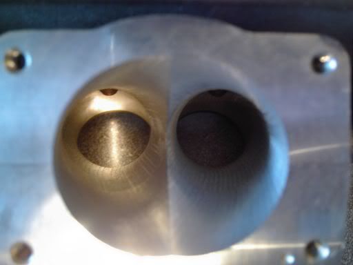
259
-
Guy Croft
- Site Admin
- Posts: 5039
- Joined: June 18th, 2006, 9:31 am
- Location: Bedford, UK
- Contact:
Re: Swirl in a 4 valve per cyl head
Believe me if they could make the ports parallel they would. There are other design considerations that affect the layout and size of the ports.
G
G
- Attachments
-
- Vauxhall HS 2.3 with very big inlet valves ..
- HS.JPG (161.15 KiB) Viewed 9761 times
-
- and big parallel ports makes for very high flow but...
- HS flowtest closeup.JPG (27.91 KiB) Viewed 9761 times
-
- a very long head....
- Vaux HS 2.3 top view.JPG (21.65 KiB) Viewed 9761 times
-
- and if you want big valves and big port entry with room for head bolts and cooling passages you invariably end up with a rather awkward port shape that has to be 'hogged out' to borderline 'break-thru' to get a head like the Vauxhall 2L XE to bhp levels over 275bhp
- XE.jpg (111.18 KiB) Viewed 9761 times
-
PersonaGrata
- Posts: 52
- Joined: October 8th, 2009, 6:42 pm
Re: Swirl in a 4 valve per cyl head
Is the controlling section a natural consequence of the following?
1.Siamese port leading to multiple inlet valves per cylinder (need for a splitter)
2.Physical limitations of where you can place circularly symetrical valves in a cylinder head - coupled with size limitations of those valves
3.The neccesity of easing the transition of gas into the cylinder such that good flowrates are possible (along with tumble etc). A straight pipe opening abruptly into a cylinder head wouldn't flow as well?
Just one more thought....
Nozzles can acheive Cd values of up to 0.99. What would be the maximum possible Cd value of a section of straight pipe of a similar length??
-
Guy Croft
- Site Admin
- Posts: 5039
- Joined: June 18th, 2006, 9:31 am
- Location: Bedford, UK
- Contact:
Re: Swirl in a 4 valve per cyl head
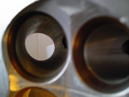
1,2 yes, 3 not necessarily see photo.
As for Cd on a straight 'smooth' pipe even there you'll have a viscous loss which is a function of fluid, pipe length and diameter, even the smooth tubes shown on the SOHC Fiat (that made 165bhp on a 1400 engine) had 3cfm loss.
G
As for Cd on a straight 'smooth' pipe even there you'll have a viscous loss which is a function of fluid, pipe length and diameter, even the smooth tubes shown on the SOHC Fiat (that made 165bhp on a 1400 engine) had 3cfm loss.
G
- Attachments
-
- bored-out downdrafted SOHC - this head still has swirl offsets on the ports.
- KM_02.JPG (116.88 KiB) Viewed 9749 times
-
PersonaGrata
- Posts: 52
- Joined: October 8th, 2009, 6:42 pm
Re: Swirl in a 4 valve per cyl head
There are so many different aspects to this discussion that I would love to continue, but it seems sensible to concentrate on the original question.
After many moons puzzling I've come to this conclusion for what its worth:
4v heads modified by hand are likely to have different characteristics from one side of an inlet to the other. Thats just a natural consequence of using hand held tools into the modification process. This can have a number of different consequences.
One possible scenario is that the left hand port may flow better than the right hand port in mid lift, but the right may flow better than left in high lift. If this is case then an anti clockwise swirl might develop initially only to be slowed and reversed by high lift flow.
Then as the valves begin to shut, that clockwise swirl will be counteracted by the flow conditions at low lift.
At best that’s a bit of a waste, and it seems that the closer the ports are to each other in performance the more likely that this scenario will occur.
So......perhaps it is better to ensure that one side always surpasses the other in performance – even if that is by a small amount, so that the motion of the mixture in the cylinder is at least predictable. If the difference was small then you wouldn't have to worry about velocity differences, or impact on the generation of pressure waves as the valves shut.
??
-
WhizzMan
- Posts: 459
- Joined: August 13th, 2010, 8:05 pm
- Location: Amsterdam, the Netherlands
Re: Swirl in a 4 valve per cyl head
Commercial manufacturers that want to create extra swirl in the cylinder at partial load do this because they want direct injected fuel to be mixed the proper way. This is usually only at partial load. They use valves, throttles and such in inlet ports to direct/restrict flow that can be set to "neutral" for unimpeded flow at high and full load.
I think you should consider what cost this swirl will give you and if it will weigh against the benefits you are getting from it. Cylinder scavenging with 4 valves per cylinder is less of an issue than with a 2 valve setup. Better mixing available fuel with air is something that will usually be limited to specific circumstances and inducing swirl at one circumstance may be handicapping mixture and scavenging at others. Limiting flow in one of the 2 inlet channels will create a "buffer" of overpressure in that channel that will also disrupt flow in the other channel, due to buffeting and such effects at the splitting point. This may be fine and give you the effect you are looking for at part throttle, but it will almost inevitably cost power at full throttle.
Please don't read this the wrong way. The last thing I want you to think is that what you are doing is stupid and it will never work. I would love to see someone figure this out and find a way to make it all work. It's just that I think that you should carefully consider the other aspects as well and not focus purely on swirl. It would be a shame if you would put an engine together and then find out you should have thought of these earlier.
Book #348
-
1NRO
- Posts: 123
- Joined: June 22nd, 2006, 4:46 pm
- Location: Carlisle
- Contact:
Re: Swirl in a 4 valve per cyl head
I just can't see how deliberately hindering flow in one of a pair of ports would be sensible, there's merit in what your looking to achieve IMO but if the effort was going to be made it'd be best to get cams ground like Mr Vizard talks about. Be warned though, he's got the patent on this and pursues infringment, it would take mightly persuasion.
259
-
PersonaGrata
- Posts: 52
- Joined: October 8th, 2009, 6:42 pm
Re: Swirl in a 4 valve per cyl head
It wouldn't be a case of inhibiting flow in any port - just spending a bit more effort on one side to ensure that it outperformed the other just enough to be measured. I.e. the range of operations performed would be identical, but greater care take to ensure that one side just outperforms the others. Because the difference in flow would be slight, there would be very very little difference in velocity at the splitter reducing the chance of disruptive flow across it.
In fact, I'm pretty sure that wont be neccessary to bias the ports for the outside two cylinders because the manifold will ensure that the outer ports are favoured. There is nothing I can do about this anyway - without spacing out the carbs better and getting a new manifold made up. So its a bit of fait accompli for those cylinders.
In terms of cost to max power, it seems that the relationship between flow figures and BHP is probabilistic (i.e. more flow more likely to gain you power than loose you power) and non-linear (an increase of 10% does not mean an increase of 10% in power), so for me the gamble of sacrificing one or two CFM on one side is worth taking if the result is the chance of a better burn and less advance.
I'm not sure about the scavenging issue at all - is it more to do with overlap periods, exhaust primary length and the included angle of the combustion chamber?
PS. I don't think David Vizard has anything to worry about. I'm not following the Polyquad pattern which has many more features than I'm proposing here!
thank you
Iain McL
-
Guy Croft
- Site Admin
- Posts: 5039
- Joined: June 18th, 2006, 9:31 am
- Location: Bedford, UK
- Contact:
Re: Swirl in a 4 valve per cyl head
Sorry I am unable to contribute of late but I am impressed with the calibre of the discussion and the way it is being presented.
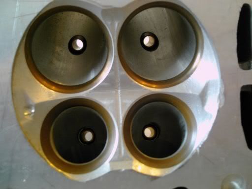
BTW - It will not suprise any of you to know that you often get a disparity between barrels when porting anyway!
GC
BTW - It will not suprise any of you to know that you often get a disparity between barrels when porting anyway!
GC
- Attachments
-
- barrel-barrel 20v.JPG (58.47 KiB) Viewed 9455 times
Who is online
Users browsing this forum: No registered users and 95 guests